

The performance of electric motors, related to consumption, torque and speed, are prescribed by technical standards. These involve the relationship between current, torque, and rotational speed.
The IEE regulations for electric motors are designed to ensure safety, efficiency, and conformity to performance standards. Electric motors must conform with efficiency standards (energy consumption), such as the Corporate Average Fleet Efficiency (CAFE) standards, which require specific energy consumption levels for vehicles including electric motors.
For example, recent studies found electric motors and motor systems in industrial applications (such as pumps, fans and compressors in buildings) are responsible for over 50% of the world’s total electricity consumption.
Most electric motors are designed to run at an approx. 50% to 100% of rated load; efficiency is usually near 80% of the rated load. The power which is consumed by the electric motor is the losses incurred in making the conversion of electrical to mechanical energy. Hence to minimize electric power consumption, motor losses must be decreased and the electrical motor efficiency must be increased. New technologies offer the potential to reduce the energy demand of motor systems across the global economy over 20% with short payback periods.
The performance characteristics of electric motors, related to torque and speed, are prescribed by technical standards that involve the relationship between current, torque, and rotational speed.
Regenerative braking systems use electric motors to slow the vehicle while simultaneously charging the battery, and they also must meet safety and efficiency regulations.
Electric motors must be constructed in accordance with safety standards to prevent electrical and mechanical hazards (such as sound levels); for these reasons should be addressed issues such as electrical wiring ad its insulation. To overcome any potential problem, analysis is needed to ensure that all motors produced are running as per national and international standards. Should be assured that all motors are delivering as per the expectation and are not causing any production loss for the OEM.
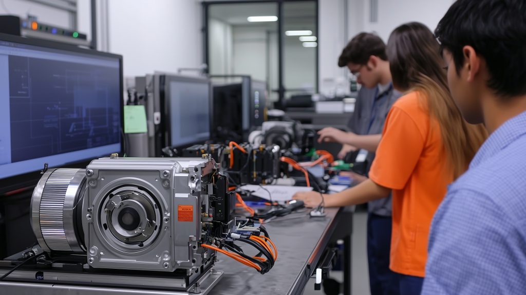
Electric motor testing
Electric motor testing is fundamental to ensuring the machines the motor is installed on safe, reliable and efficient. All the tests, conducted throughout the production stages to installation and maintenance stage, provide essential information about the electrical motor’s overall health. Electric motor testing improves reliability because identifies potential issues and allows for proactive maintenance to prevent breakdowns and extend the motor’s lifespan.
While the specific tests conducted will depend on the motor type, its application and its complexity, some of the key tests refer to the parameters being evaluated; some of them are mechanical type and other electrical type although the difference between them is nuanced.
Vibration testing detects any imbalances or misalignments, noise testing evaluates the acoustic characteristics against sound standards and thermal testing is used to monitor the electrical motor temperature to prevent overheating. Thermal testing is also used for maintenance to detect any mechanical problems that may arise during daily operation.
Electrical testing includes polarity checks and voltage level measurements, dynamic tests to see how the motor behaves in transient states, insulation tests to ensure that the motor insulation does not degrade during operation. Insulation tests include high potential (hi-pot) tests and overvoltage tests (surge test), they are geared to find weaknesses in coil-to-coil and phase-to-phase insulation that can lead to electrical failures.
Depending on the parameters and characteristics to evaluate there are many different types of instruments used in electric motor testing.
The power analyzer measures electrical parameters such as voltage and current to diagnose electrical connections, while the megohmmeter measures the insulation resistance of motor windings to detect insulation failure or degradation. The tachometer measures the rotational speed of a motor while torque transducer measures torque by converting mechanical rotation into an electrical signal.
Thermal camera captures temperature variations to identify hotspots, cooling issues and mechanical problems such as misalignment, shaft imbalance, looseness, bearing wear.
Electric motor thermography
Thermal imaging is a technique that uses infrared technology to detect and visualize temperature changes. This method is based on the principle that all objects emit thermal energy, which can be captured and represented as a thermal image. Thermal energy refers to the infrared radiation emitted by objects based on their temperature. The amount of this energy an object emits is determined by its emissivity, which varies based on the properties of the material. Thermal imaging cameras can detect overheating and circuit overload issues in electrical and mechanical systems. In industrial inspections, a thermal imaging camera is a valuable tool for detecting overheated components, insulation failures, and other potential problems that may not be visible to the naked eye. Thermal imaging cameras can identify hot spots in electrical inspections, highlighting areas at risk of overheating or fire.
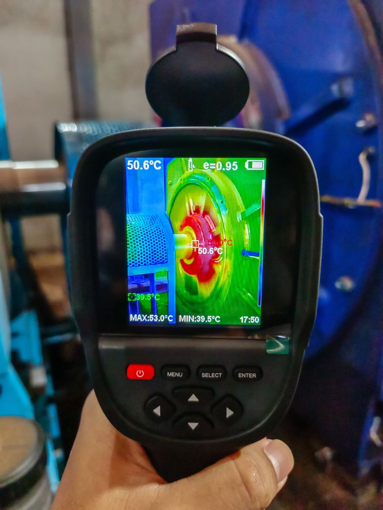
Thermal camera can see what’s going on while the electrical motor is running. Seeing a motor’s heat signature under normal operating conditions can tell a lot about its condition. Inspecting an electric motor under low load helps to highlight even minor problems, because as the load increases, so does the temperature, and if there is a problem, any small temperature difference will be amplified.
All objects emit infrared energy, known as a heat signature. An infrared camera detects and measures the infrared energy of objects. The camera converts that infrared data into an electronic image that shows the apparent surface temperature of the object being measured.
An infrared camera contains an optical system that focuses the infrared energy onto a special detector chip (a sensor array) that contains thousands of detector pixels arranged in a grid.
Each pixel in the sensor array reacts to the infrared energy focused on it and produces an electronic signal. The camera’s processor takes the signal from each pixel and applies a mathematical calculation to create a color map of the apparent temperature of the object. Each temperature value is assigned a different color. The resulting color matrix is sent to the camera’s memory and display as a temperature image (thermal image) of that object.
Fluke’s IR-Fusion technology combines a visible light image with a thermal infrared image in a pixel-by-pixel alignment; the intensity of the visible light image and the infrared image can be varied to more clearly see the problem in the infrared image or to locate it within the visible light image. This technique is essential for applications that require pinpointing the source of the problem.
In addition to basic thermal imaging capabilities, infrared cameras are available with a wide range of additional features that automate functions: they enable voice annotation, record and stream video of images, and support analysis and reporting.
(by Dario Gozzi)


