

The three-phase induction motors are widely used in several applications where the efficiency is important to contain the consumptions.
The aim of this study is to design and compare three-phase induction motors with aluminum and copper cage to fulfill the IE3 efficiency level according to typical performance and standard constraints. The proposed study has concerned TEFC, 400 V, 50 Hz, S1 duty three phase squirrel-cage induction motors. The motors designs, with Al and Cu cage, have been optimized in order to reach the minimum efficiency level IE3 at lowest active material costs and satisfy the physical and performance constraints of the designs, that are the motor specifications. Two motor sizes have been selected: 3 kW and 7.5 kW, 4 pole induction motors.
Introduction
The European Commission Regulation has introduced the efficiency levels for the three phase induction motors and the motors manufacturers have to adapt their production cycle and invest on development strategies for innovative and high efficient motors. The improvement of induction motor efficiency requires the use of innovative technological solutions and the optimization of the motor design, keeping construction restrictions typically adopted for these motors classes. The use of die-cast Copper rotor cage would result in attractive improvements in motor energy efficiency and could represent a valid alternative to traditional (and low cost) Aluminum cage. Figure 1 shows a prototype of die-cast copper rotor.

This paper presents a study on new induction motor designs with aluminum and copper rotor specially developed to reach the IE3 efficiency level. A comparison on technical and economic aspects will be shown. Two motor sizes have been selected: 3 kW-4 pole and 7.5 kW-4 pole, squirrel-cage, TEFC, 400 V, 50 Hz, S1 duty.
Table 1 shows, for each size, the IE3 minimum efficiency levels according to the EC Regulation No. 60034-30-1/2014.
| Rated power (kW) | Poles | Frame size | Efficiency IE3 |
| 3.0 | 4 | 100 L | 87.7 % |
| 7.5 | 4 | 132 M | 90.4 % |
The motors designs have been optimized in order to reach the minimum efficiency level IE3 at lowest active material cost and satisfy the physical and performance constraints of the designs, that are the motor specifications. The study does not take into account the costs for the die-casting and stamping processes, and the tooling cost. For the active material cost calculation, three different scenarios have been considered with different “Cu/Al” price ratio.
A suitable Optimization Procedure has been used that has allowed to find the “best design” by chancing the geometric dimensions of the stator and rotor shape, the stator winding and the stack length, in order to obtain a final optimized design whose dimensions are consistent, when possible, with the standard commercial frames.
Motor performance have been evaluated by a “lumped parameter model”. The adopted model takes into account magnetic saturation, skin effect on rotor parameters and thermal analysis. The validity of the mathematical model has been verified by means of experimental tests on several three-phase induction motors.
The paper presents the results of the IE3 optimized designs, with Al and Cu cage; these solutions have been compared in terms of performance, active material costs and advantage in size (diameter/stack length) and total weight. Moreover, it has been possible to verify if the Al and Cu technologies allow to go beyond IE3 efficiency level and fit with standard dimensions compatible with commercial housings.
Design optimization procedure
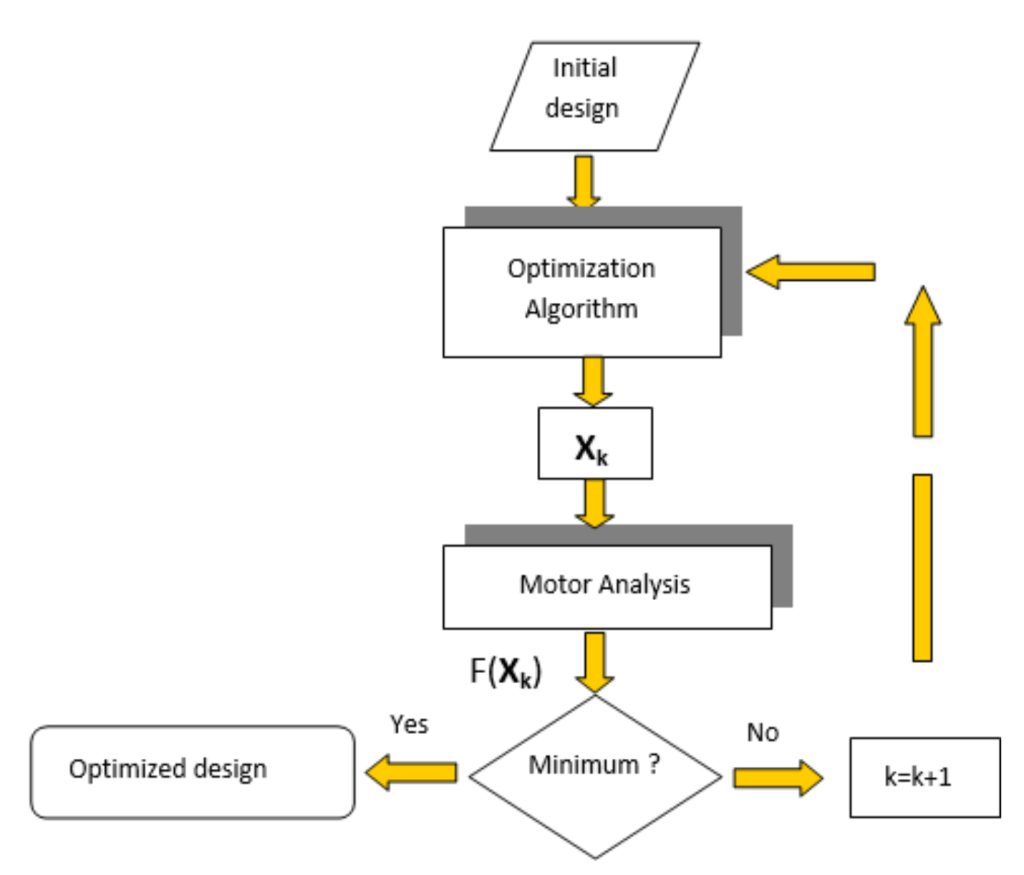
The optimization procedure is synthesized in the flow-chart shown in figure 2, where X represents the set of motor design variables and F(X) the objective function (active material cost) to minimize.
Starting from a “preliminary design” (Initial design), the optimization algorithm iteratively updates the set of design variables (X) and try to identify an “optimal” motor by making a trade-off between the different parameters of the machine.
The block “Motor Analysis” evaluates the motor performance, the objective function and the constraints values. The physical description of the motor is reduced to equivalent parameters such as resistance and inductances: the adopted model takes into account the influence of saturation on stator and rotor reactances and the influence of the skin effect on rotor parameters. The effects of the temperature on motor resistances are computed on the basis of a detailed “thermal network”. The validity of the mathematical model has been verified by means of experimental tests on several three-phase induction motors.
The motors designs, with Al and Cu cage, have been optimized in order to reach the minimum efficiency level IE3 at lowest active material costs and satisfy the physical and performance constraints of the designs, that are the motor specifications.
The active material cost (AMC) is defined as follows:
AMC = (Wfe*Cfe)+(Ww*Cw)+(Wrc*Crc) (1)
where:
- Wfe weight of gross iron kg
- Ww weight of stator winding kg
- Wrc weight of rotor cage kg
- Cfe cost of premium steel €/kg
- Cw cost of copper wire €/kg
- Crc cost of cage raw material (Al or Cu) €/kg
These costs do not take into account the die-casting process, the stamping process, the tooling and the structure costs. In order to guarantee the goodness and feasibility of the optimized designs, several constrains have been introduced that concern:
- the rated efficiency (minimum efficiency level for IE3, table 1),
- the power factor,
- the starting performance (starting torque and starting current),
- the breakdown torque, the stator winding temperature rise and rotor bars temperature rise,
- the slot fill factor.
The values of these constraints have been fixed with reference to commercial motors of the same size of the investigated motors.
Each designs variable has been varied between an upper and a lower limit according to Manufacturers suggestions, in order to obtain a final optimized design whose dimensions are consistent, when possible, with standard commercial frames.
Table 2 shows the dimensions (stack length and inner diameter) of commercial housings (type B3).
The following design assumptions have been made. For each size, the motors with Al and Cu cage have the same:
- number of stator and rotor slots,
- air-gap length,
- slot fill factor,
- stator slot opening,
- rotor skewing,
- shaft diameter,
- winding distribution and “winding factor”,
- stator slot insulation and thermal coefficients (for the thermal network).
The commercial “premium steel” 330-50 AP (0.5 mm thickness) has been chosen for the new designs.
About the active materials, the following unit price have been imposed:
- premium steel 1.0 €/kg
- copper wire 8.0 €/kg
- raw material for Al cage 2.0 €/kg
The cost of raw material for the Copper cage has been related to the Aluminum one, and the following three scenarios have been introduced by imposing a different “Cu/Al” price ratio:
- Scenario 1 – €CU / €AL = 3.0: raw material for Cu cage = 6.0 €/kg
- Scenario 2 – €CU / €AL = 3.5: raw material for Cu cage = 7.0 €/kg
- Scenario 3 – €CU / €AL = 4.0: raw material for Cu cage = 8.0 €/kg
| Frame size | Length (mm) | Inner diameter (mm) |
| 100 L | 255 | 165 |
| 132 M | 320 | 210 |
Results
The results of the optimized designs are shown in the following tables and figures that include the motor main dimensions, the motor performance and the active material weights and costs for the three scenarios, calculated according to the (1).
3 kW, 4 pole

Table 3 shows the main dimensions and performance of the 3 kW, 4 pole motor while Figures 3a, 3b, and 3c show the losses, performance (the ratio between starting current-rated current, starting torque-rated torque and breakdown torque-rated torque) and the active material costs.
Both designs have the same rated efficiency (87.7%) and the performance are quite similar and consistent with typical performance of a commercial Al motor of the same size. The copper motor exhibits a slight reduction in current and a slight increase in power factor. The staring performance are quite similar to the Al cage motor ones.

The outer stator diameters of both designs allow to use commercial housings. The Cu motor presents an advantage in size (diameter/stack length) with a total weight reduction of about 7%.
The total copper weight in the Cu motor (stator winding and rotor cage) is about 40% higher than the copper weight (stator winding) in the Al motor.
The Cu motor is slightly more expensive, with an increase on the active material cost for all cases, in the range between 3 and 10 Euro.
| h = 87.7% (IE3) | Al | Cu | |
| Stack length | mm | 155 | 150 |
| Outer stator diameter | mm | 165 | 160 |
| N. of turns x phase | 186 | 186 | |
| Wire size | mm2 | 1.64 | 1.31 |
| Weight: Gross iron | kg | 31.5 | 28.7 |
| Stator winding | kg | 4.8 | 3.5 |
| Rotor cage | kg | 1.6 | 3.2 |
| Phase current | A | 6.28 | 6.19 |
| Speed | rpm | 1468 | 1471 |
| Power factor | 0.78 | 0.79 |
7.5 kW, 4 pole
Table 4 shows the main dimensions and performance of 7.5 kW, 4 pole motor while figures 4a, 4b and 4c show the losses, performance and active material costs. Both designs have the same rated efficiency (90.4) and the copper motor exhibits a slight reduction in current and an increase in power factor.

The staring performance are quite similar to the Al cage motor ones. Difficulty to go beyond IE3 with Al technology because of limitations in housing and inability to fit with standard dimensions. The outer stator diameter of the Al cage needs a new (out of line) and more expansive housing (table 4 and table 2).
The Cu motor can use commercial housings and presents an advantage in size (diameter/stack length) with a total weight reduction of about 9%: this percentage tends to increase when a bigger housing is used for the Al cage motor. The weight of the Cu rotor cage is 49% higher than the Al cage.

Ist =starting current; Ir=rated current; Tst=starting torque; Tmax=breakdown torque; Tr=rated torque
The total copper weight in the Cu motor (stator winding and rotor cage) is about 23% higher than the copper weight (stator winding) in the Al motor.
The Cu motor presents a lower cost of active materials for the Scenario 1 with an increase for the other two cases, in the range between 2 and 7 Euro.
If the cost of the new housing for the Al motor is taken into account, the Cu motor is certainly more convenient (excluded the cost of die-casting process).
| h = 90.4% (IE3) | Al | Cu | |
| Stack length | mm | 200 | 190 |
| Outer stator diameter | mm | 215 | 210 |
| N. of turns x phase | 114 | 108 | |
| Wire size | mm2 | 4.80 | 4.15 |
| Weight: Gross iron | kg | 69.1 | 62.6 |
| Stator winding | kg | 11.0 | 8.3 |
| Rotor cage | kg | 3.5 | 5.2 |
| Phase current | A | 15.4 | 15.0 |
| Speed | rpm | 1478 | 1475 |
| Power factor | 0.78 | 0.81 |
Conclusions
In this study the three-phase induction motors with aluminum and copper cage have been compared in order to fulfill the IE3 efficiency level according to typical performance and standard constraints. Two motor sizes have been selected: 3 kW and 7.5 kW, 4 pole TEFC, 400 V, 50 Hz, induction motors.
The performance of IE3 efficiency motors with Al and Cu cage are quite similar and consistent with typical performance of commercial Al motors of the same size.
The Cu motors present always an advantage in size (diameter/stack length) and total weight. The total copper weight in the Cu motors (stator winding and rotor cage) is higher than the copper weight (stator winding) in the Al motors.
Difficulty to go beyond IE3 with Al technology for the 7.5 kW because of limitations in housing and inability to fit with standard housing dimensions.
For the 3 kW size, the Cu cage motors are slightly more expensive respect to the Al motor while for the 7.5 kW the difference on the active material could be reduced if the Al motor needs a new (out of line) housing.
It is important to remark that the costs of copper cage are affected also by the cost for the copper die-casting process and the cost of mould materials and these aspects represent now technical barriers preventing manufacture and widespread use of copper rotors. If advances will be done in the availability of durable and cost-effective mould materials, the motors with copper rotor will certainly gain more and more interest in the market as they prove to be a cost-effective way to meet the new IE4 and IE5 high efficiency standards.
Acknowledgments
This research activity was sponsored by International Copper Association. The author gratefully acknowledges Fernando Nuño, Hans de Keulenaer and Daniel Liang for their contributions.
(by Marco Villani, Department of Industrial and Information Engineering and Economics, University of L’Aquila, Italy)


